
WasherBot and DryerBot, Part 3: Connecting to the Pi and Building a Voltage Divider
03 Dec 2016Table of Contents
- Part 1: How to Tell If an Appliance Is Running
- Part 2: Current Sensors and Burden Resistors
- Part 3: Connecting to the Pi and Building a Voltage Divider
- Part 4: A Low-Pass Filter and Reading From Laundry Appliances
- Part 5: A Measurement Algorithm and Text Message Integration
Time to get started with the Pi.
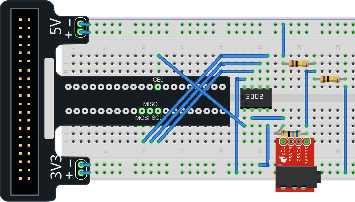
First, we need to hook the ADC up to the Pi. There are several good tutorials on this but I found this one to be the most helpful.
We’re using the SPI interface, so we want to hook up the Pi to the MCP3002 like so (note the little divot on the left side of the MCP3002 for alignment):
| MCP3002 | RPi | Reason |
|---|---|---|
| VDD | 3V3 + | Operating voltage; max voltage |
| CLK | SCLK | Clock sync |
| DOUT | MISO | Data out of the MCP3002 and into the Pi (Master In; Slave Out) |
| DIN | MOSI | Data into the MCP3002 and out of the Pi (Master Out;Slave In) |
| CS | CE0 | Chip Select - there are 2 data channels on the Pi and we’ll use the first one, 0 |
| VSS | GND (3V3 - ) | Ground (On the CanaKit breakout, it’s also called “3V3 -“ |
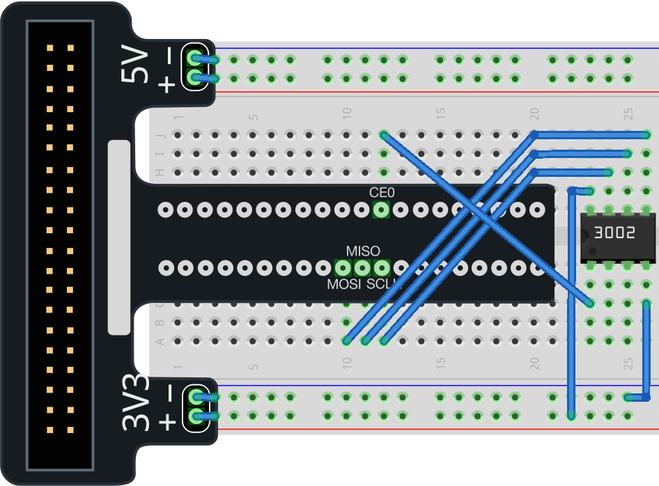
This leaves 2 pins unconnected on the MCP3002 - CH0 and CH1 - the 2 channels of data we can measure. Let’s leave them empty for now.
Programming the Pi
Now we can finally measure using the Pi. Boot into your Pi and get it into SPI mode:
sudo apt-get install python-dev python-pip
sudo modprobe spi_bcm2708
sudo pip install spidev
And download my generic measuring script
#!/usr/bin/python
#-------------------------------------------------------------------------------
# Name:        MCP3002 Measure 3V3
# Purpose:     Measure the 3V3 Supply of the Raspberry Pi
#-------------------------------------------------------------------------------

import spidev # import the SPI driver
from time import sleep

DEBUG = False
vref = 3.3 * 1000 # V-Ref in mV (Vref = VDD for the MCP3002)
resolution = 2**10 # for 10 bits of resolution
calibration = 0 # 38 # in mV, to make up for the precision of the components

# MCP3002 Control bits
#
#   7   6   5   4   3   2   1   0
#   X   1   S   O   M   X   X   X
#
# bit 6 = Start Bit
# S = SGL or \DIFF SGL = 1 = Single Channel, 0 = \DIFF is pseudo differential
# O = ODD or \SIGN
# in Single Ended Mode (SGL = 1)
#   ODD 0 = CH0 = + GND = - (read CH0)
#       1 = CH1 = + GND = - (read CH1)
# in Pseudo Diff Mode (SGL = 0)
#   ODD 0 = CH0 = IN+, CH1 = IN-
#       1 = CH0 = IN-, CH1 = IN+
#
# M = MSBF
# MSBF = 1 = LSB first format
#        0 = MSB first format
# ------------------------------------------------------------------------------


# SPI setup
spi_max_speed = 1000000 # 1 MHz (1.2MHz = max for 2V7 ref/supply)
# reason is that the ADC input cap needs time to get charged to the input level.
CE = 0 # CE0 | CE1, selection of the SPI device

spi = spidev.SpiDev()
spi.open(0,CE) # Open up the communication to the device
spi.max_speed_hz = spi_max_speed

#
# create a function that sets the configuration parameters and gets the results
# from the MCP3002
#
def read_mcp3002(channel):
    # see datasheet for more information
    # 8 bit control :
    # X, Strt, SGL|!DIFF, ODD|!SIGN, MSBF, X, X, X
    # 0, 1,    1=SGL,     0 = CH0  , 0   , 0, 0, 0 = 96d
    # 0, 1,    1=SGL,     1 = CH1  , 0   , 0, 0, 0 = 112d
    if channel == 0:
        cmd = 0b01100000
    else:
        cmd = 0b01110000

    spi_data = spi.xfer2([cmd,0]) # send hi_byte, low_byte; receive hi_byte, low_byte

    # receive data range: 000..3FF (10 bits)
    # MSB first: (set control bit in cmd for LSB first)
    # spidata[0] =  X,  X,  X,  X,  X,  0, B9, B8
    # spidata[1] = B7, B6, B5, B4, B3, B2, B1, B0
    # LSB: mask all but B9 & B8, shift to left and add to the MSB
    adc_data = ((spi_data[0] & 3) << 8) + spi_data[1]
    return adc_data

try:
    print("MCP3002 Single Ended CH0,CH1 Read of the 3V3V Pi Supply")
    print("SPI max sampling speed = {}".format(spi_max_speed))
    print("V-Ref = {0}, Resolution = {1}".format(vref, resolution))
    print("SPI device = {0}".format(CE))
    print("-----------------------------\n")

    while True:
        print (read_mcp3002(0), read_mcp3002(1))


except KeyboardInterrupt: # Ctrl-C
    spi.close()

def main():
    pass

if __name__ == '__main__':
    main()
run it, and you should see output like this:
MCP3002 Single Ended CH0 Read of the 3V3 Pi Supply
SPI max sampling speed = 1000000
V-Ref = 3300.0, Resolution = 1024
SPI device = 0
-----------------------------

(0,0)
(0,0)
(0,0)
(1,0)
(0,0)
(0,2)
(0,0)
(0,0)
Since no current is flowing through the CH0 and CH1 pins, they are essentially at zero volts. There can be some error in the measurement, but it’s close enough.
Measuring Some Voltage
Cool, now let’s see the high end of the scale. We can measure up to 3.3V. Let’s hook up CH0 to the 3V3 rail with a 10kOhm resistor to prevent damaging the Pi:
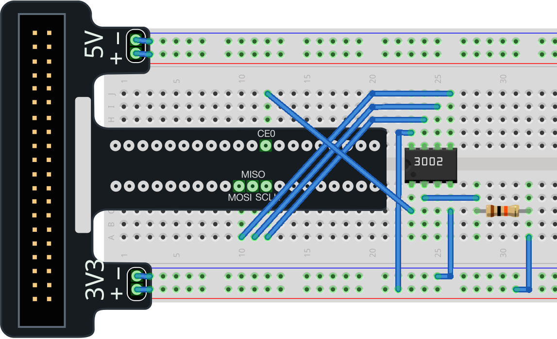
Measure again:
MCP3002 Single Ended CH0 Read of the 3V3 Pi Supply
SPI max sampling speed = 1000000
V-Ref = 3300.0, Resolution = 1024
SPI device = 0
-----------------------------

(1023,0)
(1023,0)
(1023,0)
(1023,0)
(1023,0)
(1023,0)
(1023,0)
Cool, we’ve measured the top of the range and the bottom of the range!
Let’s measure some real voltage from the CT sensor:
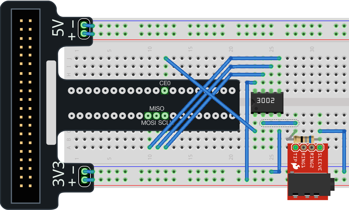
Now, the CT sensor is connected to GND across a 68 Ohm resistor. When no current flows through the CT sensor, we will read 0V. We put the CT sensor around a 12A space heater and echo the output of the measure program to text:
python measure.py >> heater.txtI took that and plotted it in Excel:
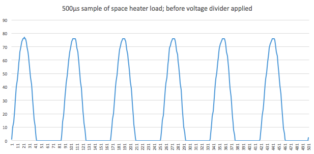
One thing to notice is that we’re only getting half of the information about the AC wave. This is because when the wave is at its peak, we’re pushing voltage toward the GND pin. When the wave is in a trough, it’s trying to push voltage back toward the 3V3 pin to no avail and the MCP3002 still reads it as 0V.
We need to get the steady-state voltage up to a higher amount so that we can still read a positive voltage with the MCP3002. How about halfway?
Voltage Divider
Resistors create something called a “voltage drop” which is some EE wizardry that I don’t understand. Take it for granted that when you have a resistor, the voltage on one terminal is measurably and proportionally different to the voltage on the other terminal. We can exploit this principle to put our circuit at that “steady state” I mentioned before.
By connecting two resistors in series and then measuring the voltage in between them, we can obtain a desired voltage that is a specific fraction of the input voltage. This arrangement is called a voltage divider.
Here’s a good resource for learning more about voltage dividers
From the equations there, we postulate that if we have 2 resistors of equal resistance connected in series, then the voltage between them will be exactly half the input voltage.
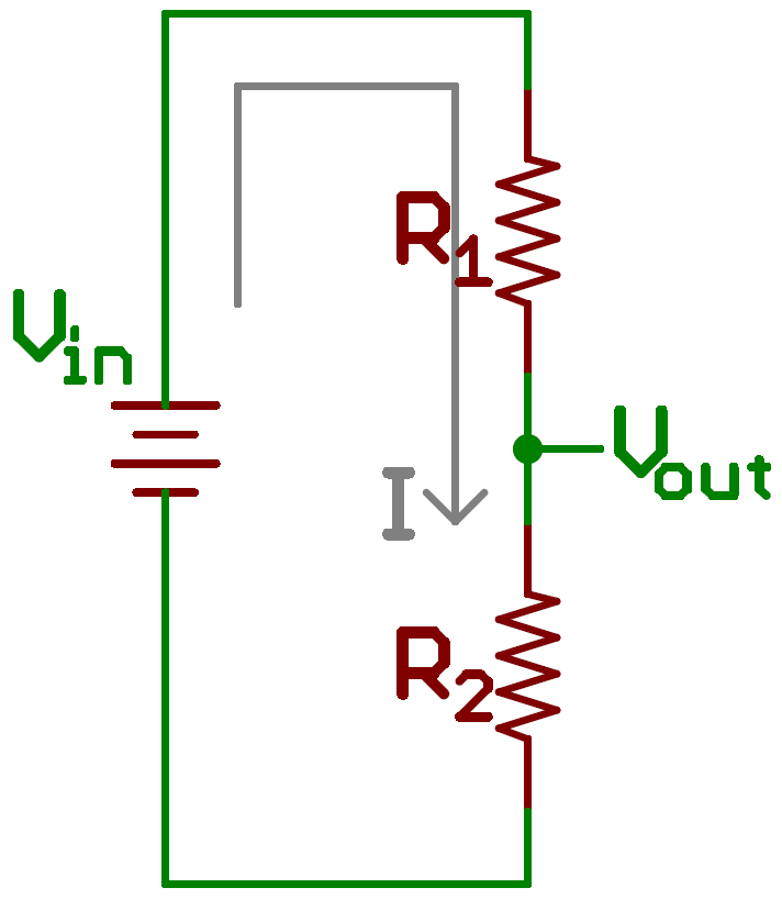 R1 = R2 = 100kOhm
I’ll use 100kOhm resistors to lessen the amount of current this circuit will drain from the Pi in case I use a battery pack.
Let’s measure the heater again:
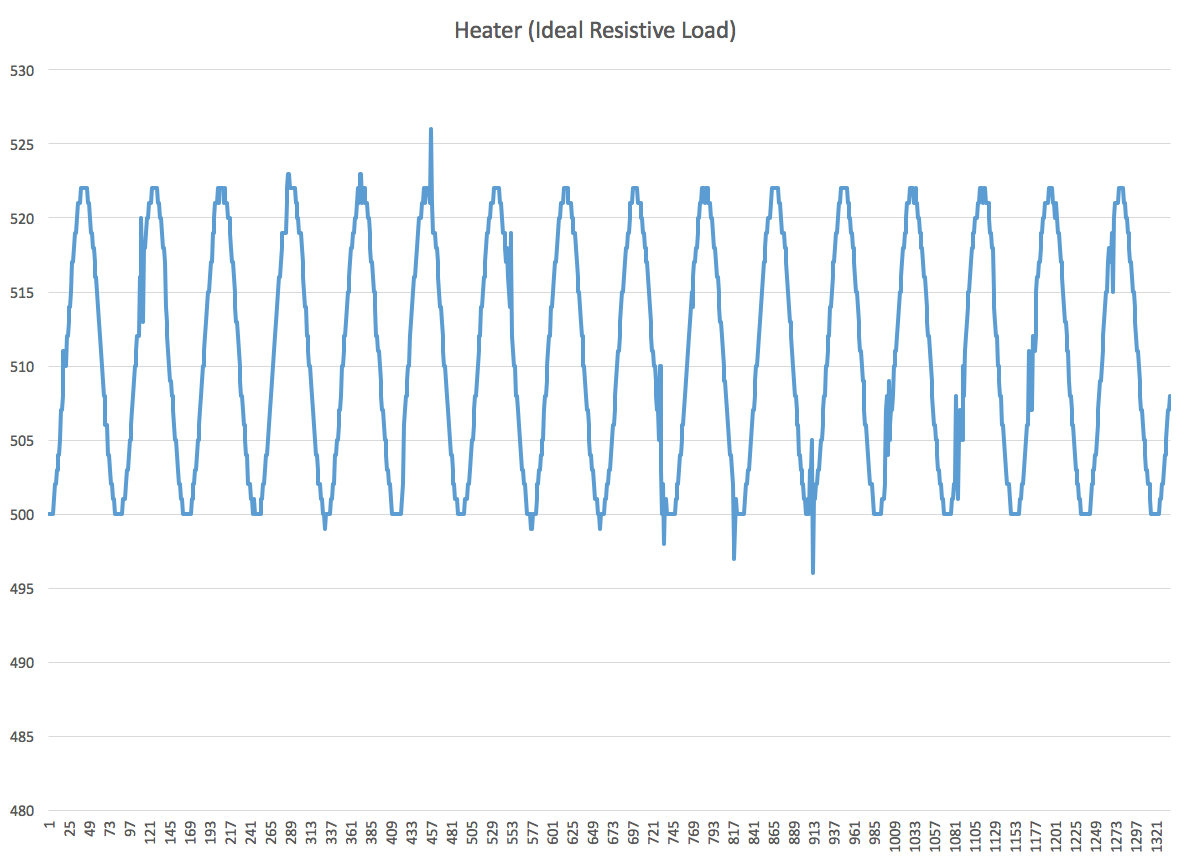
Cool. We can now see the full AC sine wave of this space heater - which is an ideal resistive load, always using a consistent amount of power. You’ll noticed it’s centered around 1/2 of our 10-bit scale: 511.5.
How about something that’s not a perfect load?

…neat.