
WasherBot and DryerBot, Part 2: Current Sensors and Burden Resistors
22 Nov 2016Table of Contents
- Part 1: How to Tell If an Appliance Is Running
- Part 2: Current Sensors and Burden Resistors
- Part 3: Connecting to the Pi and Building a Voltage Divider
- Part 4: A Low-Pass Filter and Reading From Laundry Appliances
- Part 5: A Measurement Algorithm and Text Message Integration
As you read in Part 1, I’ve now got a plan to get my washer and dryer to talk to me.
- Clip a CT sensor to the power line.
- Hook the CT sensor up to an analog-to-digital converter
- Connect that ADC to a Raspberry Pi
- Write some software for the Pi to measure power consumption and notify me.
Off to SparkFun.com for some parts.
First, 2 CT sensors to measure our current. 30 amps should be fine:
Non-Invasive Current Sensor - 30A
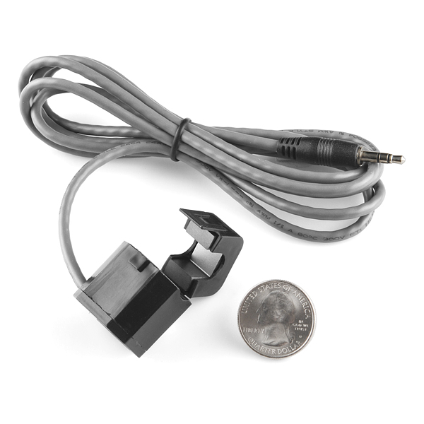
You’ll notice that these come with 3.5mm TRS plugs on the end. This will make them easy to plug in and remove, but now I need a jack to receive them.
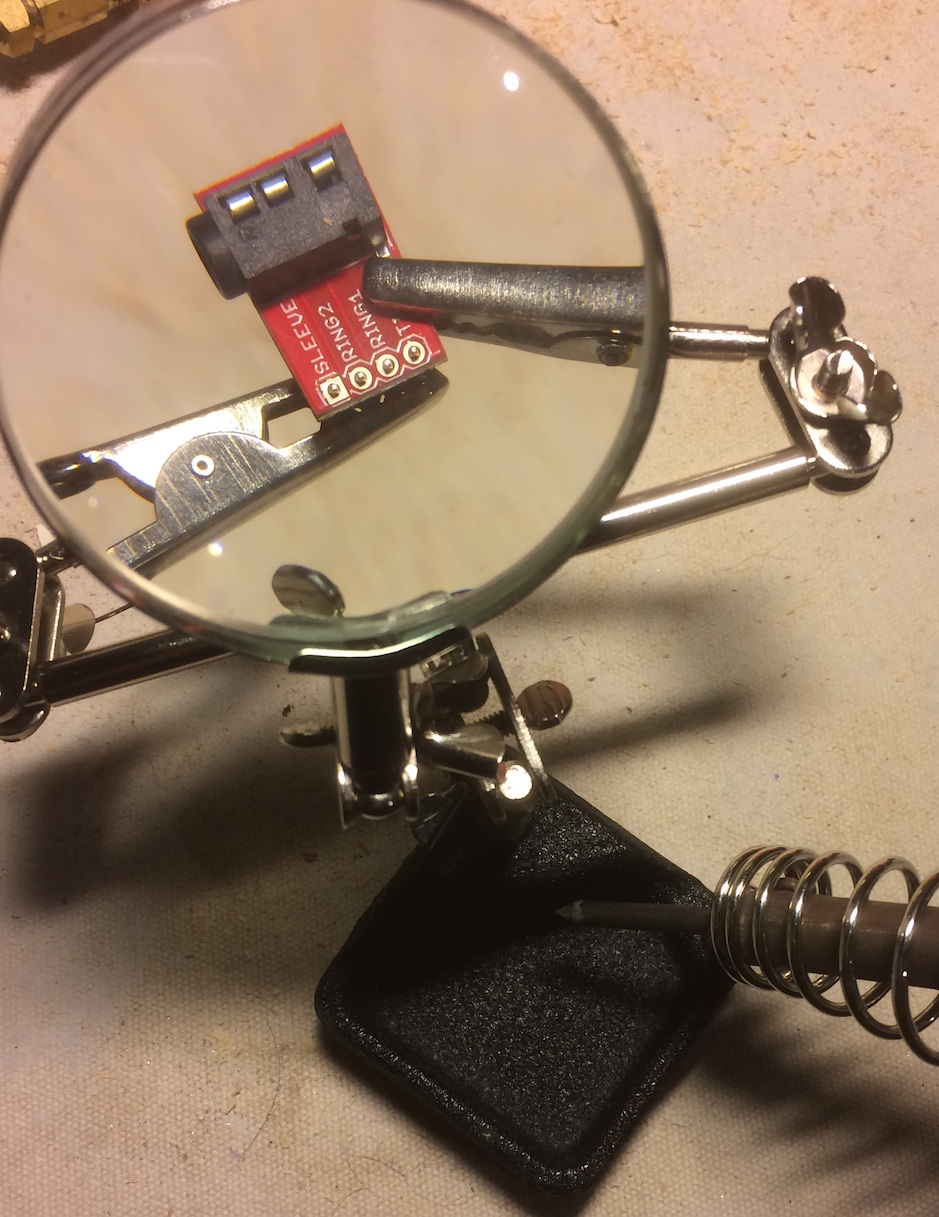
SparkFun TRRS 3.5mm Jack Breakout
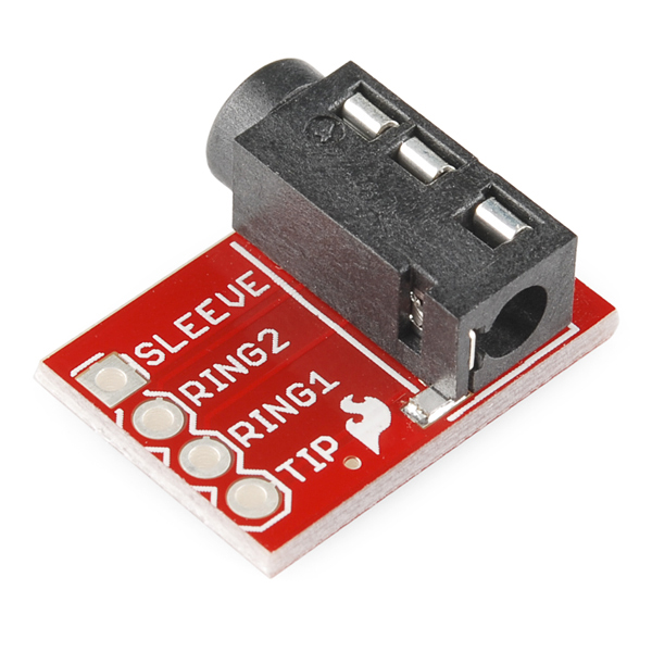
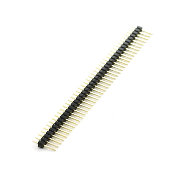
These jacks come already assigned to a breakout board, which will make it convenient to use them with a breadboard - once some headers are soldered on:
Break Away Headers - Straight
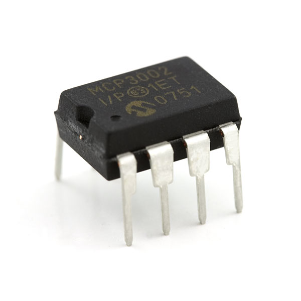
Lastly, I actually need to buy the ADC mentioned in part 1:
Analog to Digital Converter - MCP3002
Soldering
Once the parts arrived, I needed to solder the header pins onto the jack breakout for attaching to the breadboard. I’d never soldered delicate electronics, only larger wires so I picked up some 0.32 solder and watched some tutorials.
With the parts soldered and prepared, it’s time to start measuring.
Measuring Current
So a little math here. According to the datasheet, our current sensor has a 2000-turn ratio. This means a current of 30 Amps, divided by 2000 turns, will yield a resultant current of 15mA. What voltage will that current be at? Well, theoretically, an infinite voltage (I don’t quite understand why this is, but I trust the opinion of people smarter than me). If you just hook the CT up to a multimeter, that meter will have resistance in the circuit and so you’ll get a “voltage drop” across the two leads of the multimeter.
And so we get to measuring a 100-Watt lightbulb with just the multimeter hooked to it for a test. Turns out, with a measly 0.8 A of current, we’re already up to 2V. This won’t do. I need a way to get the voltage down further.
Burden Resistor
To get the voltage down further, I learned I need to use a burden resistor. This is a resistor with a very specific resistance that matches your circuit in order to get to an expected voltage range. This site has some great details and an Excel-based calculator for burden resistor resistance.
The key bit is that our maximum measurable voltage is 3.3V - that’s the potential we’re feeding into the MCP3002. Since we’re measuring AC current, it means that 3.3V is the peak-to peak meaning that we actually want to measure a max of 1.65V as our zero-point or reference point. At the maximum peak of the AC wave, we’ll have 1.65V reference + 1.65V from the sensor = 3.3V. At the minimum trough of the AC wave, we’ll have 1.65V - 1.65V = 0V.
The equation for burden resistor calculation is:
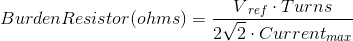
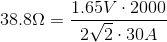
With a 30A current, we’d have a burden resistor value of 38.8 Ohms.
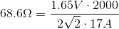
Since RadioShack had 68 Ohms as the closest resistor value (heh), I can actually measure up to 17A safely:
So we have a circuit that won’t overvolt the Pi! In part 3, we’ll hook the sensor up to the Pi and start measuring it.