WasherBot and DryerBot, Part 4: A Low-Pass Filter and Reading From Laundry Appliances
09 Dec 2016Table of Contents
- Part 1: How to Tell If an Appliance Is Running
- Part 2: Current Sensors and Burden Resistors
- Part 3: Connecting to the Pi and Building a Voltage Divider
- Part 4: A Low-Pass Filter and Reading From Laundry Appliances
- Part 5: A Measurement Algorithm and Text Message Integration
When I was following the OpenEnergyMon guide I noticed they were including a capacitor in their circuit:
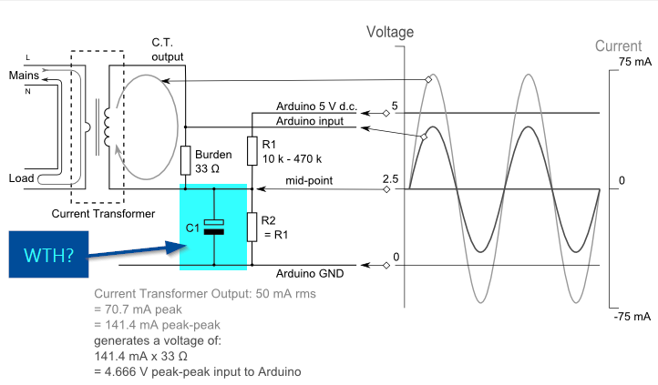
What’s that there for? It’s to provide an alternative path for some of the current to flow to the ground. Capacitors take some time to charge up and then discharge all at once, in a way that is dependent on the frequency of the current flowing through them. An arrangement like this with a resistor and a capacitor together is called a low-pass filter, meaning that only signals with a low frequency will be able to pass. It will filter out excess noise.
This is another great discussion on the subject.
Let’s hook up a 10uF capacitor to our circuit:
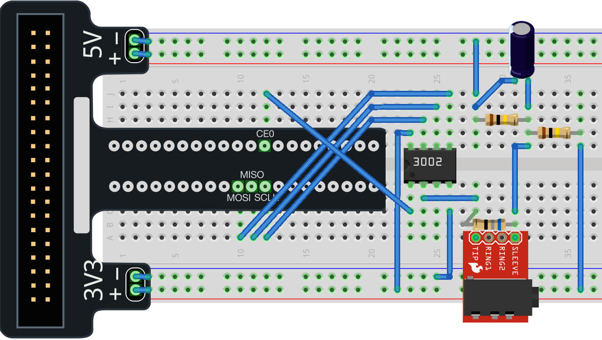
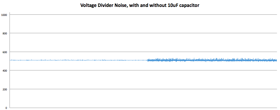
I did some experimenting by measuring the voltage signal with and without the low-pass filter.
Across the entire range of the ADC:
and zoomed in:
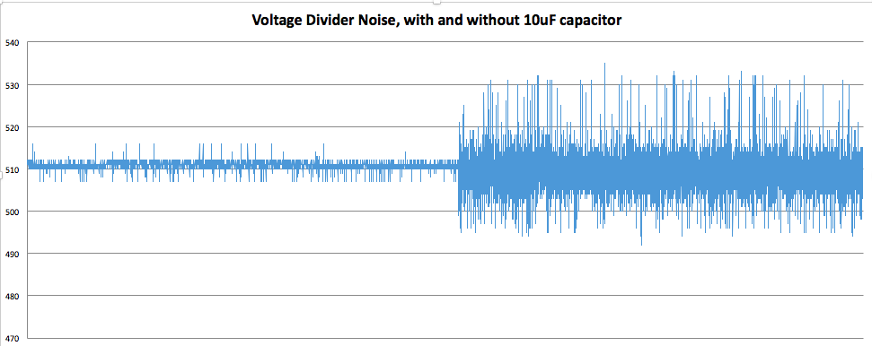
As you can see, it’s not trivial. A perfectly clean signal would measure 511 every time, but there’s some jitter. With the low-pass filter, the difference between the maximum value and the minimum is around 15. Without the filter, it’s much as 50. To a crude approximation, the filter adds around 10% accuracy to our measurement.
Two Jacks and Two Channels
Up to this point, we’ve only been measuring one input at a time. With 2 channels, the MCP3002 can read 2 voltages. And with 2 laundry appliances, that’s what I need to do.
We’ll add a second jack to the circuit:
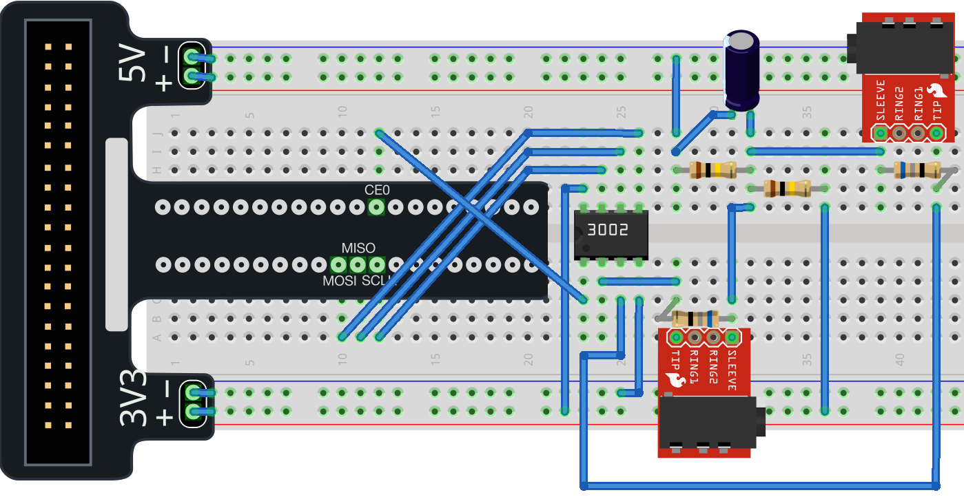
We can share the same voltage divider, and direct our output to channel 1.
Measuring the Real Appliances
Now, in order to translate voltage readings into the state of the appliance, I need to actually measure the appliances. I turned the breaker off to the dryer, unplugged it, and took off the back cover to fit the current sensor around 1 of the wires. A 220V dryer in the US has 4 wires coming into it. The green ground, 2 phases of power (red and black) and a white neutral. After some trial and error, I found that my dryer had the heating element powered by the left phase and the motor powered by the right phase.
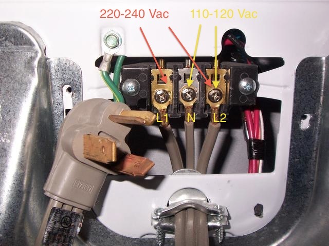
For the washer, I turned off the breaker to the outlet it was plugged into and put the current sensor around the power line inside the outlet.
I cued up the measurement script and took some readings of the dryer:

It was basically perfect. I was excited here - the washer reading stays almost exactly at baseline and the dryer reading starts out there. When the dryer turns on, it is instantaneously recognizable in the graph.
In Part 5, I’ll show you my algorithm for turning thousands of measurements into a single meaningful data point.